ESP32-S2 Thermostatic Control With Resistive Heating and NST112
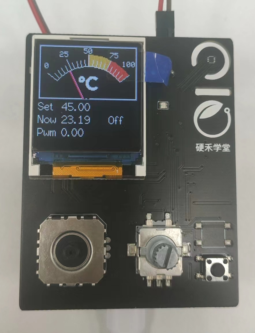
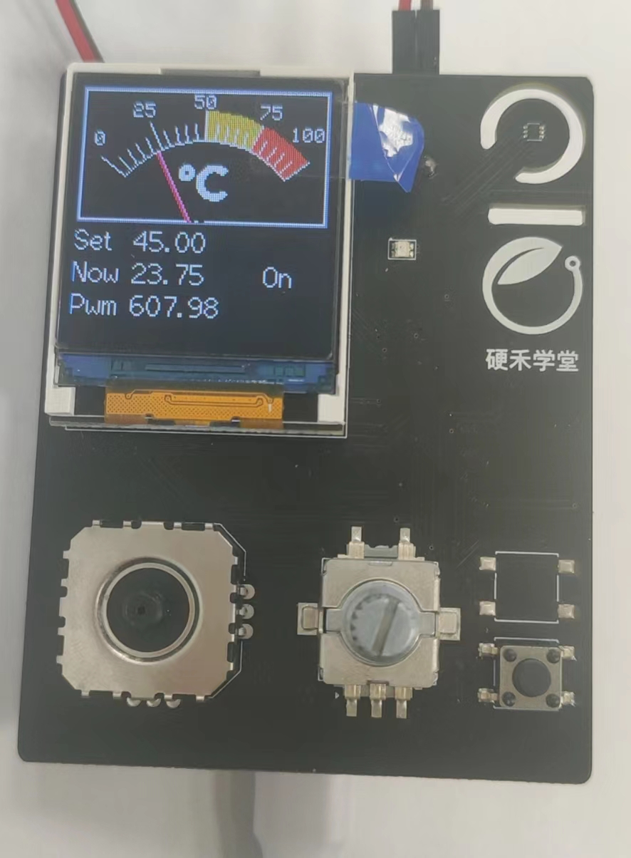
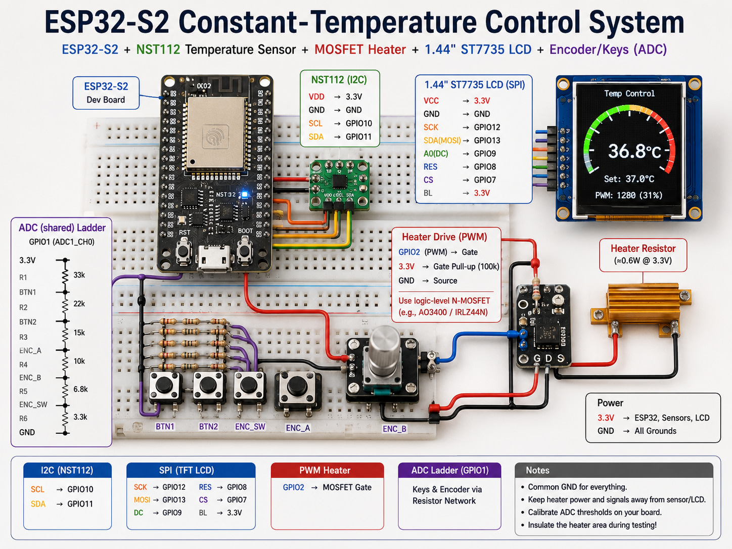
This project implements a constant-temperature control loop on an ESP32-S2 learning kit: a resistive heater warms a small insulated area, an NST112 digital temperature sensor reports board temperature, and a 1.44\" ST7735 LCD shows a gauge-style readout. PWM drives a MOSFET heater switch; a PID-style regulator adjusts duty cycle. A shared ADC pin reads a resistor-ladder network for keys and a rotary encoder.
Assumption: Exact GPIO assignments, schematic net names, and complete User_Setup.h for TFT_eSPI match your vendor board package—treat the snippets below as patterns, not a full firmware drop-in.
Hardware overview
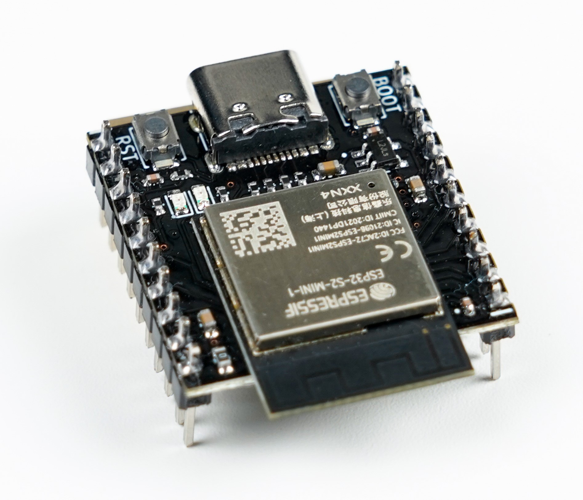
ESP32-S2 module board
The ESP32-S2 is a single-core Xtensa LX7 SoC focused on 2.4 GHz Wi‑Fi, rich GPIO, and USB programmability under ESP-IDF or Arduino. Typical dev boards add USB-C, buttons, LEDs, and two headers that break out usable IO.
On-module highlights (family-level):
- ESP32-S2-MINI-1 module family (Espressif PDF)
- 2.4 GHz Wi‑Fi, no Bluetooth on S2 (plan accordingly).
- 4 MB flash (and optional PSRAM variants depending on exact module).
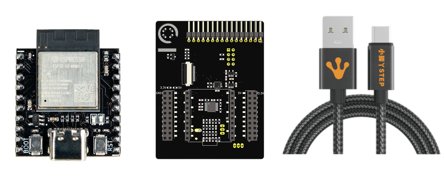
Expansion board
The IO expansion board used here provides:
- Keys and rotary encoder (routed through an analog resistor network).
- Dual potentiometer inputs.
- RGB LED.
- 1.44\" 128×128 LCD on SPI (ST7735-class).
- MMA7660 accelerometer.
- Heater resistor + MOSFET stage.
- NST112 temperature sensor (I2C).
- Breakout to the ESP32-S2 core module.
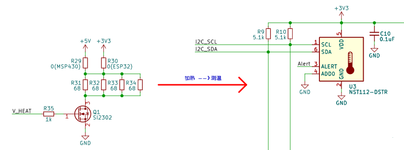
Control concept
The heater raises board temperature when the MOSFET conducts. Firmware reads temperature, compares to a setpoint, and updates PWM duty to regulate average power. Vendor math for the heater network (illustrative): (P \approx U^2 / R_\text{eq}) with 3.3 V rails and parallel 68 Ω elements yields on the order of ~0.6 W—enough for a demo hotspot when insulated (verify on your schematic).
Toolchain
- PlatformIO + VS Code for build, flash, and libraries.
- A serial terminal (CoolTerm, PuTTY, PIO monitor, and so on) for debug traces.
Firmware uses the Arduino framework on ESP32-S2 for fast bring-up.
Firmware architecture
Functional blocks:
- Read NST112 over I2C.
- Render UI with TFT_eSPI (gauge-style view adapted from TFT_eSPI analog meter examples).
- Output LEDC PWM to the heater MOSFET gate path.
- Sample ADC quickly to decode encoder steps and button states from the resistor ladder.
NST112 temperature read
The NST112-DSTR is a small digital sensor with a simple register model. Below is a compact init/read pattern; 7-bit address and register bytes must match your board wiring and datasheet configuration.
#include <Arduino.h>
#include <Wire.h>

static const uint8_t kNst112Addr7 = 0x48;
static const uint8_t kRegSet = 0x01;
static const uint8_t kRegTemp = 0x00;
static const float kLsbC = 0.0625f;
static const uint8_t kNumBits = 12;

static const uint8_t kCfg0 = 0b01100000;
static const uint8_t kCfg1Base = 0b11100000;

void nst112Init() {
  Wire.begin();
  Wire.beginTransmission(kNst112Addr7);
  Wire.write(kRegSet);
  Wire.write(kCfg0);
  Wire.write(static_cast<uint8_t>(kCfg1Base | ((kNumBits == 13) ? (1u << 4) : 0)));
  Wire.endTransmission();
}

float nst112ReadC() {
  uint8_t msb = 0;
  uint8_t lsb = 0;

  Wire.beginTransmission(kNst112Addr7);
  Wire.write(kRegTemp);
  Wire.endTransmission(false);
  const uint8_t got = Wire.requestFrom(static_cast<int>(kNst112Addr7), 2, static_cast<int>(true));
  if (got == 2) {
    msb = Wire.read();
    lsb = Wire.read();
  }

  uint16_t raw = static_cast<uint16_t>((msb << 8) | lsb);
  raw >>= (kNumBits == 13) ? 3 : 4;
  return static_cast<float>(raw) * kLsbC;
}
Note: Configure conversion rate / averaging per the Novosns datasheet for your accuracy goals; the constants above follow the original coursework sketch.
LCD gauge (TFT_eSPI)
The coursework UI uses TFT_eSPI with an analog meter renderer and a moving needle (analogMeter(), plotNeedle(), bitmap assets). That code is lengthy and tightly coupled to sprite sizes and font indices—keep it in your repository and tune User_Setup.h for ST7735, SPI pins, and rotation.
Heater PWM (LEDC)
Use LEDC to generate a stable PWM for the MOSFET driver:
const int kPwmPin = /* your GPIO */;
const int kLedcChannel = 0;
const uint32_t kPwmFreqHz = 20000;   // example; pick what your gate driver filters allow
const uint8_t kResolutionBits = 12;  // 0..4095 duty span

void heaterPwmInit() {
  pinMode(kPwmPin, OUTPUT);
  ledcSetup(kLedcChannel, kPwmFreqHz, kResolutionBits);
  ledcAttachPin(kPwmPin, kLedcChannel);
}
High duty increases average heater power; low duty reduces it. Always respect safe temperature limits and insulation—demo boards are not industrial ovens.
PID-style regulation
The original project uses a position PID with integral separation to limit overshoot; in testing, PD-like tuning was often sufficient because the plant is slow and inertial.
Bugfix vs a common coursework paste: constrain() returns a value—assign it back to the target variable.
struct PositionPid {
  float Kp, Ki, Kd;
  float Integral;
  float LastErr;
  float Output;
  float OutputMin, OutputMax;
  float I_outputMin, I_outputMax;
  float Integraldead_zone;
  int index;
};

float singlePidPosition(PositionPid* pid, float target, float measure) {
  if (!pid) return 0.0f;

  const float err = target - measure;

  pid->index = (fabs(err) > pid->Integraldead_zone) ? 0 : 1;

  pid->Output = pid->Kp * err + pid->Kd * (err - pid->LastErr);
  pid->Integral += pid->Ki * err * static_cast<float>(pid->index);

  pid->Output = constrain(pid->Output, pid->OutputMin, pid->OutputMax);
  pid->Integral = constrain(pid->Integral, pid->I_outputMin, pid->I_outputMax);

  pid->Output += pid->Integral;
  pid->Output = constrain(pid->Output, pid->OutputMin, pid->OutputMax);

  pid->LastErr = err;
  return pid->Output;
}
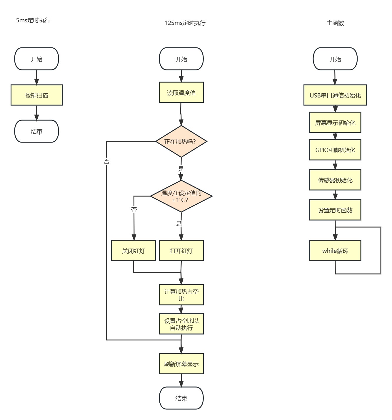
Control loop rate
If the sensor update path is 8 Hz, run the regulator on the same cadence (125 ms) so measurement and actuation stay aligned—typically a hardware timer or a Ticker callback that:
- Reads temperature.
- Updates PID output.
- Writes
ledcWrite(channel, duty). - Refreshes the on-screen values / needle.
Serial telemetry fix: match format specifiers to arguments (original code printed two floats with a mismatched format string in one branch).
void onControlTick() {
  const float tempNow = nst112ReadC();
  float pwm = singlePidPosition(&gPid, gTargetC, tempNow);
  pwm = constrain(pwm, 0.0f, 4095.0f);

  if (!gHeaterEnabled) {
    pwm = 0.0f;
    ledcWrite(kLedcChannel, 0);
    return;
  }

  ledcWrite(kLedcChannel, static_cast<uint32_t>(pwm));

  char line[48];
  snprintf(line, sizeof(line), "{Temp}%.2f,%.2f\r\n", gTargetC, tempNow);
  Serial.print(line);
  snprintf(line, sizeof(line), "{PWM}%.0f\r\n", pwm);
  Serial.print(line);
}
Encoder and keys through one ADC
The expansion board multiplexes encoder phases and buttons into one ADC node via resistor dividers. At ~200 Hz sampling, step patterns differ for clockwise vs counter-clockwise rotation; the firmware thresholds raw codes against calibrated ADC centers.
Example ADC traces from the coursework (CW rotation, CCW rotation, encoder push, key):
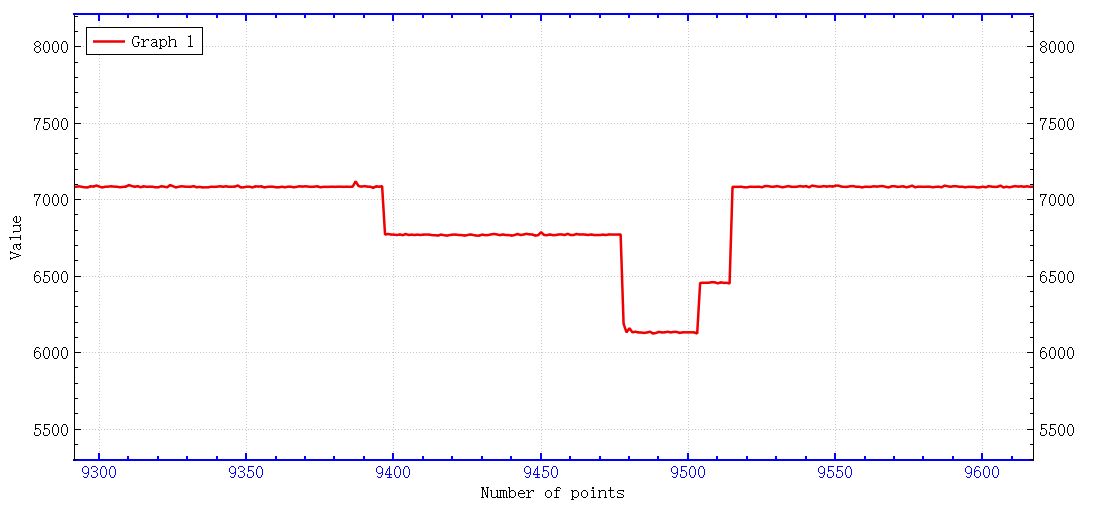
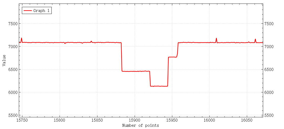
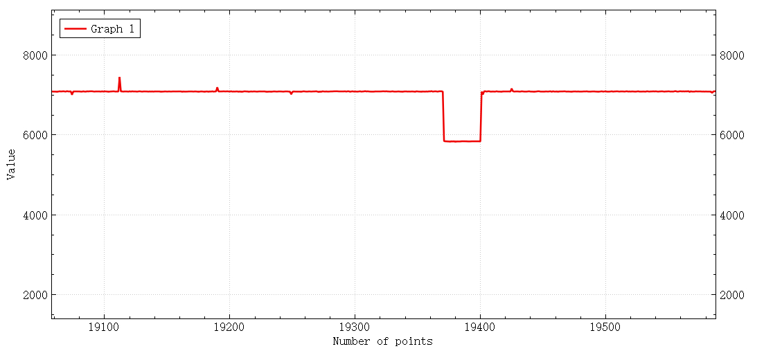
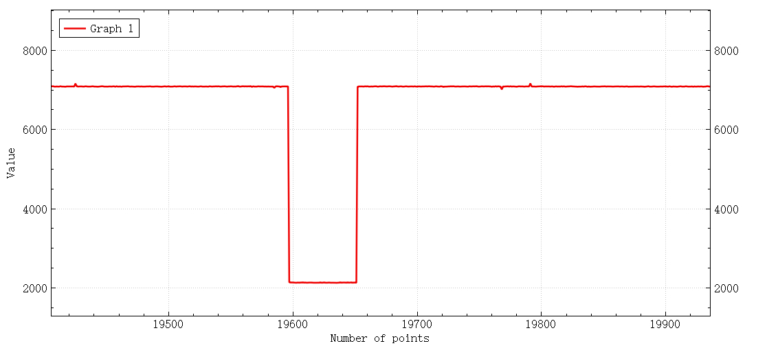
Decoding logic measures baseline ADC bins (ADC_Val[] in the original), applies a tolerance window, and infers rotation direction by the sequence of minima between states. Keep calibration values in flash or EEPROM if you move between boards.
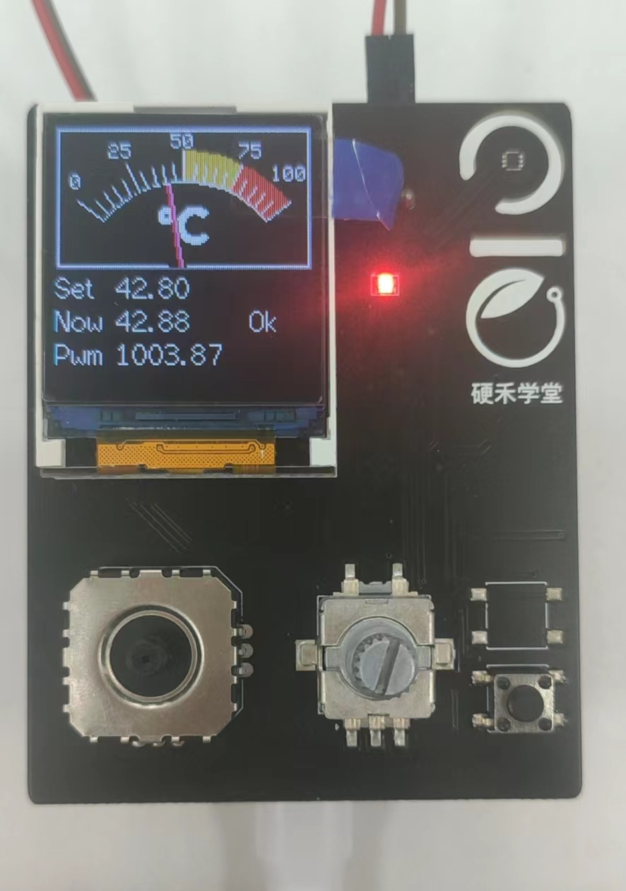
Operation
- Encoder push: toggles heating on/off.
- Key: selects which digit of the setpoint you edit (tens / ones / tenths in the original UX).
- Rotate: bumps the selected digit CW/CCW.
- When |error| < ~1 °C (stricter than an earlier ±3 °C coursework spec in the source notes), the UI shows OK and status LEDs reflect regulation state.
Challenges and tuning notes
- ADC ladder decoding is the trickiest UX piece: you need fast, clean sampling and calibrated thresholds per board.
- Thermal inertia is large: expect to lean on derivative action and conservative integrator windup limits; validate always with a real temperature probe if you care about absolute accuracy.
Next improvements
Polish the HMI, harden noise rejection on the ADC channel, and persist calibration constants per device.