PCF8574 GPIO Expansion for ESP32 (Quick Guide)

Need more GPIO on ESP32 without changing the MCU? PCF8574 is a low-cost I2C expander that adds 8 digital I/O pins per chip, up to 64 pins with 8 addresses.
This short guide covers only the essentials: when to use it, how to wire it, and the minimum code to get it working.
When PCF8574 Is the Right Choice
Use it for low-speed digital tasks:
- LEDs
- Buttons
- Relays
- Matrix keypads
Avoid it for timing-critical outputs such as high-speed PWM.
Key Limits You Must Remember
- Voltage: 2.5V to 6V
- I2C addresses: 0x20 to 0x27 (A0/A1/A2)
- Pins: 8 quasi-bidirectional GPIO
- Strong sink current, weak source current
Practical rule: drive LEDs in active-low mode.
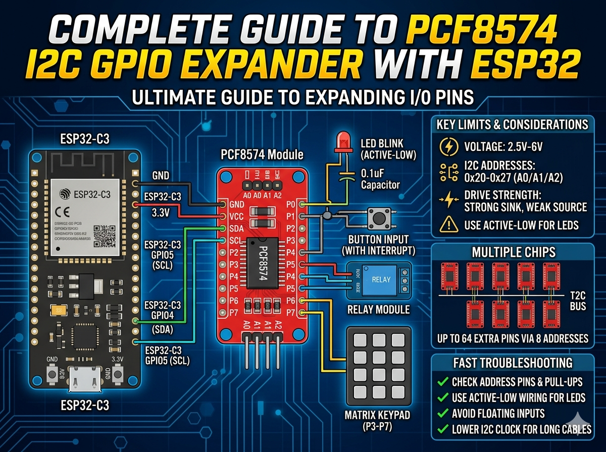
Wiring with ESP32-C3
Example pin map:
Make sure SDA and SCL have pull-up resistors (often already on the module).
Library Setup
PlatformIO:
Minimal Code: Scan + Blink
First scan I2C to confirm the address, then blink an LED on P0.
#include <Arduino.h>
#include <Wire.h>
#include <PCF8574.h>

PCF8574 pcf(0x20);

void scanI2C() {
  Serial.println("I2C scan:");
  for (uint8_t addr = 1; addr < 127; addr++) {
    Wire.beginTransmission(addr);
    if (Wire.endTransmission() == 0) {
      Serial.print("Found: 0x");
      if (addr < 16) Serial.print('0');
      Serial.println(addr, HEX);
    }
  }
}

void setup() {
  Serial.begin(115200);
  Wire.begin(4, 5, 400000);
  scanI2C();

  if (!pcf.begin()) {
    Serial.println("PCF8574 init failed");
    while (true) delay(1000);
  }
}

void loop() {
  pcf.digitalWrite(0, LOW);   // LED ON (active-low)
  delay(500);
  pcf.digitalWrite(0, HIGH);  // LED OFF
  delay(500);
}
Input and Interrupt Notes
- For input behavior, write HIGH before reading a pin.
- For buttons, connect the button to GND (pressed = LOW).
- Use INT pin if you want event-driven input instead of polling.
Multi-Chip Expansion
Set A0/A1/A2 differently per board to use 0x20 to 0x27. One bus can control 8 chips.
If communication becomes unstable, reduce I2C speed to 100kHz and shorten wiring.
Fast Troubleshooting
- No device found: check address pins, SDA/SCL swap, pull-ups.
- LED not lighting: use active-low wiring.
- Random input reads: avoid floating input, improve wiring and grounding.
- Occasional bus errors: lower clock rate and reduce cable length.
Takeaway
PCF8574 is one of the simplest ways to expand ESP32 GPIO for low-speed control. If you follow active-low output wiring, proper I2C pull-ups, and correct address setup, it is reliable and easy to scale.