ESP32 HDS10 Condensation Sensor Guide
The HDS10 is a condensation sensor designed for dew alarm applications. If you search for it online, you will mostly find product listings and brief parameter sheets, but very few practical ESP32 examples. This article turns the datasheet into a usable ESP32 workflow.
The key point is simple: you must not drive the HDS10 like a normal analog sensor. The sensor voltage must stay below 0.8 V, so the recommended resistor network from the manufacturer is not optional. Once the circuit is correct, the ESP32 ADC can read the output directly and detect condensation reliably.
Understand the HDS10 operating principle first
The HDS10 is a positive characteristic switch-type humidity element. In this application, its resistance increases as humidity approaches condensation. That behavior is the opposite of many common humidity-sensitive resistors.
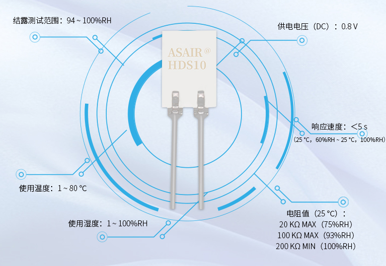
According to the manufacturer information shown in the draft material:
- The sensor operating voltage is limited to 0.8 V DC.
- At 75% RH, the sensor resistance is up to 20 kOhm.
- At 93% RH, the sensor resistance is up to 100 kOhm.
- At 100% RH, the sensor resistance is at least 200 kOhm.
- Typical applications include dew alarm systems, HVAC equipment, storage, instruments, and environmental monitoring.
This means the ESP32 should not measure the sensor resistance directly with a simple pull-up to 3.3 V. Use the recommended divider so the sensor remains in its safe voltage range.
Use the recommended resistor network
The correct conclusion is that the HDS10 must be used with a current-limiting and scaling network. The datasheet circuit shown in the source material uses these values:
- R1 = 300 kOhm from 5 V to Vout
- R2 = 50 kOhm from Vout to GND
- HDS10 in parallel with R2
- Vout connected to an ESP32 ADC pin
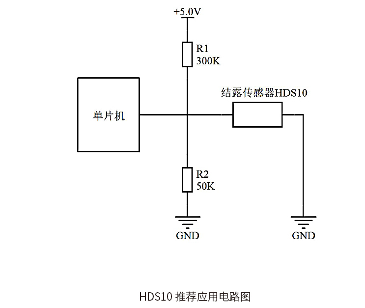
This network does two jobs:
- It protects the sensor by keeping the sensor voltage below the 0.8 V limit.
- It converts the humidity-dependent resistance into a voltage that the ESP32 ADC can sample.
Do not connect the HDS10 directly to 3.3 V or 5 V. That risks damaging the sensor.
Estimate the voltage range before writing code
The practical conclusion is that condensation causes Vout to rise. With the recommended circuit, you can derive a safe starting threshold before calibration.
First compute the equivalent resistance of the sensor and R2:
- Req = (RH x R2) / (RH + R2)
Then compute the output voltage:
- Vout = 5.0 x Req / (R1 + Req)
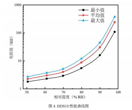
Using the values from the source material, the expected range is approximately:
| Condition | Assumed sensor resistance | Estimated Vout |
|---|---|---|
| Dry room air | 15 kOhm | 0.185 V |
| Near condensation | 100 kOhm | 0.500 V |
| Condensation starts | 200 kOhm | 0.588 V |
| Heavy condensation | 500 kOhm | 0.714 V |
Assumption: the dry-state resistance can vary significantly with environment and installation. Treat the table above as a calibration starting point, not a final threshold for every board.
Read the sensor with the ESP32 ADC
The main implementation advice is to measure Vout, not the sensor resistance. Because the expected voltage is below 0.8 V, the ESP32 ADC can sample it directly.
The example below targets Arduino core for ESP32 3.x and uses hysteresis plus repeated confirmation to avoid false alarms near the switching point.
#include <Arduino.h>

constexpr int HDS10_ADC_PIN = 34;
constexpr float DEW_ON_MV = 500.0f;
constexpr float DEW_OFF_MV = 450.0f;
constexpr int REQUIRED_CONSECUTIVE_SAMPLES = 3;
constexpr unsigned long SAMPLE_INTERVAL_MS = 1000;

bool dewDetected = false;
int highCount = 0;
int lowCount = 0;
unsigned long lastSampleMs = 0;

void setup() {
  Serial.begin(115200);
  analogReadResolution(12);
  analogSetPinAttenuation(HDS10_ADC_PIN, ADC_0db);
}

void loop() {
  if (millis() - lastSampleMs < SAMPLE_INTERVAL_MS) {
    return;
  }

  lastSampleMs = millis();

  uint32_t voltageMv = analogReadMilliVolts(HDS10_ADC_PIN);
  Serial.print("HDS10 voltage: ");
  Serial.print(voltageMv);
  Serial.println(" mV");

  if (!dewDetected) {
    if (voltageMv >= DEW_ON_MV) {
      highCount++;
      lowCount = 0;
      if (highCount >= REQUIRED_CONSECUTIVE_SAMPLES) {
        dewDetected = true;
        Serial.println("Condensation detected");
      }
    } else {
      highCount = 0;
    }
  } else {
    if (voltageMv <= DEW_OFF_MV) {
      lowCount++;
      highCount = 0;
      if (lowCount >= REQUIRED_CONSECUTIVE_SAMPLES) {
        dewDetected = false;
        Serial.println("Condensation cleared");
      }
    } else {
      lowCount = 0;
    }
  }
}
This example uses 500 mV as the initial dew trigger and 450 mV as the release threshold. Those values match the draft calculations and add a small hysteresis window for stability.
Calibrate the threshold on real hardware
The correct engineering approach is to calibrate your own board instead of trusting one theoretical threshold. Component tolerances, ADC variation, sensor placement, airflow, and contamination can all shift the measured voltage.
Use this workflow:
- Log Vout in a dry room for several minutes.
- Expose the sensor to a high-humidity environment close to condensation.
- Record the voltage at the first reliable dew event.
- Set the trigger slightly below that measured value.
- Set the release threshold lower than the trigger value to create hysteresis.
If your application is safety-critical, add a moving average or median filter and store calibration values in non-volatile memory.
Watch these hardware limits
The practical conclusion here is that circuit protection matters more than software polish.
- Keep the sensor voltage below 0.8 V at all times.
- Measure the divider output Vout, not the sensor directly.
- Sample every 1 to 2 seconds; the datasheet response time is under 5 seconds, so fast polling is usually unnecessary.
- Avoid operation below 0 degrees Celsius if ice formation is possible.
- Place the sensor where condensation is expected to appear first, not deep inside a warm enclosure.
The source material also notes that the sensor is intended for dew alarm scenarios such as HVAC, humidifiers, dehumidifiers, storage, and instrumentation. That matches the simple threshold-based detection method shown above.
Conclusion
The HDS10 can be used with an ESP32 reliably, but only if you respect the sensor's 0.8 V limit and use the recommended resistor network. In practice, the ESP32 ADC sees a rising voltage as humidity approaches condensation, which makes dew detection straightforward.
Start with a trigger around 0.50 V, add hysteresis and repeated confirmation, then calibrate the final threshold on your actual hardware. That gives you a much more reliable result than treating the HDS10 as a generic analog humidity sensor.
References
- Aosong HDS10 product page: https://www.aosong.com/Products/info.aspx?lcid=&proid=86
- HDS10 datasheet figures and parameter tables from the manufacturer material referenced in the original draft