Attitude Sensor
The attitude sensor allows the development board to detect if it's being picked up, sense vibrations, determine if it's standing upright or lying flat, and detect whether it's stationary or in motion. With this sensor, you can create intelligent projects.
The attitude sensor on the development board is the QMI8658 model, which integrates a 3-axis accelerometer and 3-axis gyroscope. It supports both SPI and I2C communication. On our development board, we use I2C communication. The ESP32-S3 has only one I2C peripheral, and all I2C devices on our development board share the same I2C communication interface. Communication is determined by the I2C device address, with the QMI8658 having a 7-bit I2C address of 0x6A.
In this example, we'll complete XYZ axis tilt detection and transmit the tilt data through the serial port to be displayed on the terminal.
5.1 Using the Example
Copy the provided [02-attitude] example to your experiment folder and open the project in VSCode.

Connect the development board to your computer. In VSCode, select the serial port, choose esp32s3 as the target chip, select serial download mode, then click the "One-click Triple" button and wait for compilation, download, and terminal opening.
After the terminal opens automatically, it will output the tilt angles of the XYZ axes every second, as shown below:
I (309) main_task: Calling app_main()
I (309) main: I2C initialized successfully
I (319) esp32_s3_szp: QMI8658 OK!
I (1329) main: angle_x = 3.3  angle_y = 0.2 angle_z = 3.3
I (2329) main: angle_x = 3.4  angle_y = 0.1 angle_z = 3.4
I (3329) main: angle_x = 3.2  angle_y = 0.2 angle_z = 3.3
I (4329) main: angle_x = 3.4  angle_y = 0.1 angle_z = 3.4
I (5329) main: angle_x = 3.2  angle_y = 0.0 angle_z = 3.2
Adjust the development board's orientation to see the values change. In theory, each axis's value will change from -90° to +90°.
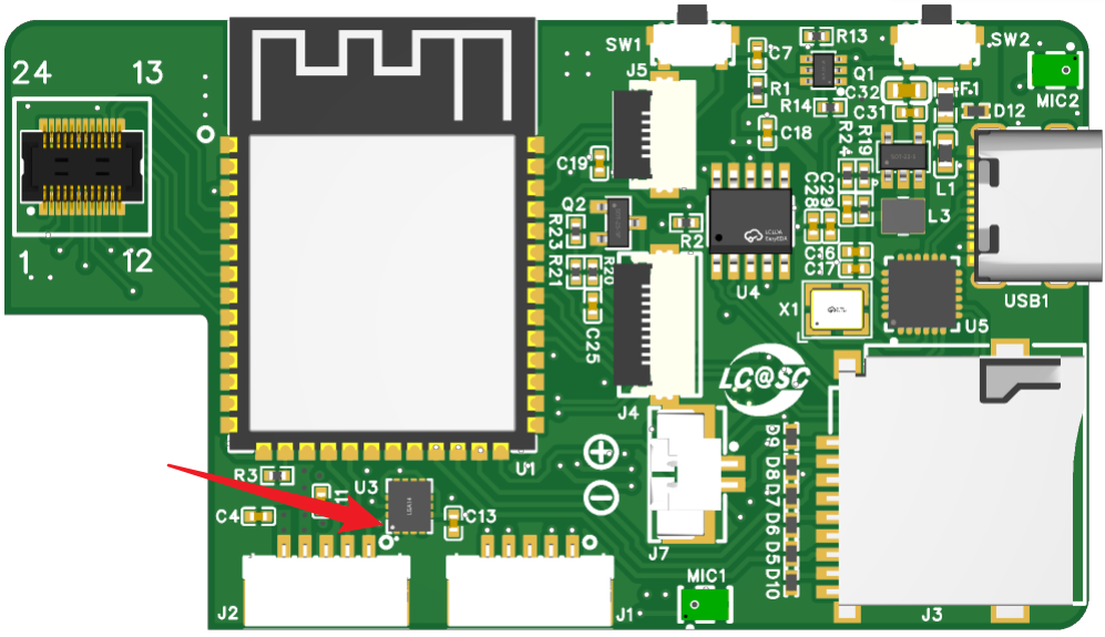
The position of the QMI8658 attitude sensor on the circuit board is shown below, with the small dot located at the bottom left corner of the chip.
Below is the coordinate direction diagram for each axis of the chip.
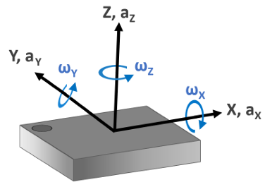
The tilt data for the X and Y directions represents the angle between the X and Y axes relative to the XY plane, or the tilt angle relative to the horizontal plane.
The Z-axis tilt data is not the angle relative to the horizontal plane, but rather the angle between the gravity vector and the Z-axis.
5.2 Example Explanation
In the main folder, besides the main.c file, there are two other files: esp32_s3_szp.c and esp32_s3_szp.h. The "szp" in esp32_s3_szp stands for "Shi Zhan Pai" (Practical), indicating that this file contains development board support functions.
The QMI8658 sensor chip communicates with the ESP32 via I2C. The esp32_s3_szp file contains two parts: I2C driver and QMI8658 driver.
Open the main.c file, which contains the following code:
#include "esp32_s3_szp.h"

static const char *TAG = "main"; // "main" in the terminal indicates this message is from main.c

t_sQMI8658 QMI8658; // Define QMI8658 structure variable

void app_main(void)
{
    ESP_ERROR_CHECK(bsp_i2c_init());  // Initialize I2C bus
    ESP_LOGI(TAG, "I2C initialized successfully"); // Output I2C initialization success message

    qmi8658_init(); // Initialize QMI8658 chip

    while (1)
    {
        vTaskDelay(1000 / portTICK_PERIOD_MS);  // Delay 1000ms
        qmi8658_fetch_angleFromAcc(&QMI8658);   // Get XYZ axis tilt
        // Output XYZ axis tilt
        ESP_LOGI(TAG, "angle_x = %.1f  angle_y = %.1f angle_z = %.1f",QMI8658.AngleX, QMI8658.AngleY, QMI8658.AngleZ);
    }
}
Find the app_main function and browse from top to bottom.
The bsp_i2c_init() function initializes the I2C bus, defined in esp32_s3_szp.c. Right-click on bsp_i2c_init() and select "Go to Definition" to quickly find the function definition (or press F12).
esp_err_t bsp_i2c_init(void)
{
    i2c_config_t i2c_conf = {
        .mode = I2C_MODE_MASTER,
        .sda_io_num = BSP_I2C_SDA,
        .sda_pullup_en = GPIO_PULLUP_ENABLE,
        .scl_io_num = BSP_I2C_SCL,
        .scl_pullup_en = GPIO_PULLUP_ENABLE,
        .master.clk_speed = BSP_I2C_FREQ_HZ
    };
    i2c_param_config(BSP_I2C_NUM, &i2c_conf);

    return i2c_driver_install(BSP_I2C_NUM, i2c_conf.mode, 0, 0, 0);
}
The I2C initialization code defines the I2C pins, master mode, pull-up resistors, and clock frequency. If the hardware PCB doesn't have pull-up resistors on the I2C bus, they must be enabled here. If the PCB has pull-up resistors, enabling them here is optional.
First execute i2c_param_config, then i2c_driver_install to complete I2C configuration. These functions are located in the IDF project folder and can't be opened by right-clicking here. To view their definitions, you need to open the esp-idf project folder in another VSCode instance.
Back in the main function, we see bsp_i2c_init() is run as a parameter of ESP_ERROR_CHECK.
ESP_ERROR_CHECK is a macro function located in esp-idf that checks function return values. If there's no error, nothing happens. If there's an error, it causes the microcontroller to restart. This macro requires including the esp_err.h header file.
The second statement in main() uses ESP_LOGI to print logs, similar to printf. The first parameter of ESP_LOGI indicates which file printed the log (here "main" indicates it's from main.c). The second parameter is the string to print. Besides ESP_LOGI, there's also ESP_LOGE for errors, with different colors in the terminal (green for info, red for errors).
Continuing in main(), qmi8658_init() initializes the QMI8658 sensor.
// Initialize QMI8658
void qmi8658_init(void)
{
    uint8_t id = 0; // Chip ID

    qmi8658_register_read(QMI8658_WHO_AM_I, &id ,1); // Read chip ID
    while (id != 0x05)  // Check if ID is 0x05
    {
        vTaskDelay(1000 / portTICK_PERIOD_MS);  // Delay 1 second
        qmi8658_register_read(QMI8658_WHO_AM_I, &id ,1); // Read ID again
    }
    ESP_LOGI(TAG, "QMI8658 OK!");  // Print message

    qmi8658_register_write_byte(QMI8658_RESET, 0xb0);  // Reset
    vTaskDelay(10 / portTICK_PERIOD_MS);  // Delay 10ms
    qmi8658_register_write_byte(QMI8658_CTRL1, 0x40); // CTRL1 Set address auto-increment
    qmi8658_register_write_byte(QMI8658_CTRL7, 0x03); // CTRL7 Enable accelerometer and gyroscope
    qmi8658_register_write_byte(QMI8658_CTRL2, 0x95); // CTRL2 Set ACC 4g 250Hz
    qmi8658_register_write_byte(QMI8658_CTRL3, 0xd5); // CTRL3 Set GRY 512dps 250Hz
}
First read the ID to verify the chip exists. If it exists, the hardware is working.
Then configure the sensor parameters. The specific configurations can be understood from the comments, and more details can be found in the QMI8658 datasheet.
The initialization function uses two other functions: qmi8658 register write and read functions. These are located above the initialization function and use esp-idf's I2C read/write functions.
// Read QMI8658 register
esp_err_t qmi8658_register_read(uint8_t reg_addr, uint8_t *data, size_t len)
{
return i2c_master_write_read_device(BSP_I2C_NUM, QMI8658_SENSOR_ADDR, ®_addr, 1, data, len, 1000 / portTICK_PERIOD_MS);
}
// Write to QMI8658 register
esp_err_t qmi8658_register_write_byte(uint8_t reg_addr, uint8_t data)
{
uint8_t write_buf[2] = {reg_addr, data};
return i2c_master_write_to_device(BSP_I2C_NUM, QMI8658_SENSOR_ADDR, write_buf, sizeof(write_buf), 1000 / portTICK_PERIOD_MS);
}
Back in main(), we enter a while loop that reads XYZ axis tilt values every second and prints them to the terminal.
The qmi8658_fetch_angleFromAcc function gets the XYZ axis tilt values. These aren't read directly from the chip registers - the register values need to be calculated and converted using formulas. The register reading and conversion functions are defined as:
// Read accelerometer and gyroscope register values
void qmi8658_Read_AccAndGry(t_sQMI8658 *p)
{
    uint8_t status, data_ready=0;
    int16_t buf[6];

    qmi8658_register_read(QMI8658_STATUS0, &status, 1); // Read status register
    if (status & 0x03) // Check if accelerometer and gyroscope data is ready
        data_ready = 1;
    if (data_ready == 1){  // If data is ready
        data_ready = 0;
        qmi8658_register_read(QMI8658_AX_L, (uint8_t *)buf, 12); // Read accelerometer and gyroscope values
        p->acc_x = buf[0];
        p->acc_y = buf[1];
        p->acc_z = buf[2];
        p->gyr_x = buf[3];
        p->gyr_y = buf[4];
        p->gyr_z = buf[5];
    }
}

// Get XYZ axis tilt values
void qmi8658_fetch_angleFromAcc(t_sQMI8658 *p)
{
    float temp;

    qmi8658_Read_AccAndGry(p); // Read accelerometer and gyroscope register values
    // Calculate tilt values from register values and convert radians to degrees
    temp = (float)p->acc_x / sqrt( ((float)p->acc_y * (float)p->acc_y + (float)p->acc_z * (float)p->acc_z) );
    p->AngleX = atan(temp)*57.29578f; // 180/π=57.29578
    temp = (float)p->acc_y / sqrt( ((float)p->acc_x * (float)p->acc_x + (float)p->acc_z * (float)p->acc_z) );
    p->AngleY = atan(temp)*57.29578f; // 180/π=57.29578
    temp = sqrt( ((float)p->acc_x * (float)p->acc_x + (float)p->acc_y * (float)p->acc_y) ) / (float)p->acc_z;
    p->AngleZ = atan(temp)*57.29578f; // 180/π=57.29578
}
First look at qmi8658_Read_AccAndGry, which reads accelerometer and gyroscope register values. A technique is used here: initially defining a buf array with 6 16-bit elements (int16_t buf[6];). When reading registers, 12 8-bit register values are read into buf (qmi8658_register_read(QMI8658_AX_L, (uint8_t *)buf, 12);). Then when assigning values to accelerometer and gyroscope, 16-bit values are used (p->acc_x = buf[0];).
When reading registers, only a starting address QMI8658_AX_L is given, then 12 bytes are read continuously. The register definitions are in esp32_s3_szp.h. Right-click on QMI8658_AX_L and select "Go to Definition" (or press F12) to find:
.......
    QMI8658_AX_L,
    QMI8658_AX_H,
    QMI8658_AY_L,
    QMI8658_AY_H,
    QMI8658_AZ_L,
    QMI8658_AZ_H,
    QMI8658_GX_L,
    QMI8658_GX_H,
    QMI8658_GY_L,
    QMI8658_GY_H,
    QMI8658_GZ_L,
    QMI8658_GZ_H,
    ......
The X-axis value is a 16-bit number, with low byte read first, then high byte. The same applies to others.
Now look at qmi8658_fetch_angleFromAcc. This function first calls the register reading function, then calculates using formulas.
The calculation formula is shown below:

The tilt calculation statements in the function are written according to this formula. The formula results are in radians. Multiplying radians by 180/π gives degrees. In the function, we've already calculated 180/π and included it to save the microcontroller some computation time.
This only uses accelerometer values to calculate tilt, suitable for when the sensor is stationary, moving slowly, or at constant speed. In vibration scenarios, these values will have significant error and need gyroscope fusion for accurate results.
Back in main(), after calculating tilt, ESP_LOGI prints the log. This ESP_LOGI includes formatted output compared to the first one.
5.3 Example Creation Process
For the attitude sensor example, we'll use sample_project as a template. Copy sample_project to our experiment folder and rename it to 02-attitude (attitude meaning orientation). After renaming, my project path is D:\esp32s3\02-attitude.
Open the 02-attitude folder in VSCode to modify it.
First open CMakeLists.txt in the root directory and change the project name to attitude, then save and close the file.
Create two new files in the project: esp32_s3_szp.c and esp32_s3_szp.h, to store development board configuration functions. "szp" stands for "Shi Zhan Pai" (Practical).
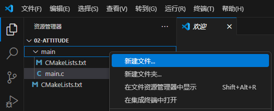
Right-click on main and select "New File".
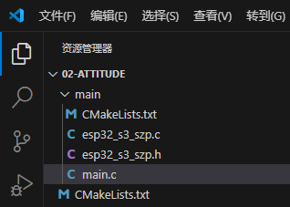
Name the new files esp32_s3_szp.c and esp32_s3_szp.h as shown:
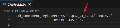
Then open CMakeLists.txt in the main folder and add esp32_s3.c. Normally this is added automatically.
Open esp32_s3_szp.h and add #pragma once at the top, equivalent to #ifndef #define #endif.
Since QMI8658 uses I2C, we'll add I2C code to esp32_s3_szp.c and .h files, referencing the official IDF example at: examples\peripherals\i2c\i2c_simple
The completed esp32_s3_szp.c file looks like:
#include <stdio.h>
#include "esp32_s3_szp.h"
#include "esp_err.h"
#include "driver/i2c.h"

esp_err_t bsp_i2c_init(void)
{
    i2c_config_t i2c_conf = {
        .mode = I2C_MODE_MASTER,
        .sda_io_num = BSP_I2C_SDA,
        .sda_pullup_en = GPIO_PULLUP_ENABLE,
        .scl_io_num = BSP_I2C_SCL,
        .scl_pullup_en = GPIO_PULLUP_ENABLE,
        .master.clk_speed = BSP_I2C_FREQ_HZ
    };
    i2c_param_config(BSP_I2C_NUM, &i2c_conf);

    return i2c_driver_install(BSP_I2C_NUM, i2c_conf.mode, 0, 0, 0);
}
写好后的 esp32_s3_szp.h 文件的内容如下:
#pragma once

#include "esp_err.h"

#define BSP_I2C_SDA           (GPIO_NUM_1)
#define BSP_I2C_SCL           (GPIO_NUM_2)

#define BSP_I2C_NUM           (0)
#define BSP_I2C_FREQ_HZ       100000

esp_err_t bsp_i2c_init(void);
点击打开 main.c 文件,添加 esp32_s3_szp.h 头文件。
在 app_main 函数中,先调用 I2C 初始化函数。
void app_main(void)
{
    ESP_ERROR_CHECK(bsp_i2c_init());
    ESP_LOGI(TAG, "I2C initialized successfully");
}
函数里使用到了 ESP_LOGI,需要包含 esp_log.h 头文件,写到 esp32_s3_szp.h 文件中就可以。
还需要给 ESP_LOGI 里面的 TAG 定义一下,这个定义放到 app_main 函数的前面。
接下来,开始写 qmi8658 的驱动函数。
我们先写两个读取 qmi8658 寄存器的函数和写入 qmi8658 寄存器的函数。写入函数用于配置传感器的参数,读取函数用于读取传感器的寄存器数据,例如 ID 号,状态等。这两个函数放入 esp32_s3_szp.c 文件中。这两个函数,也是参考官方 i2c_simple 例程中的修改的。
esp_err_t qmi8658_register_read(uint8_t reg_addr, uint8_t *data, size_t len)
{
return i2c_master_write_read_device(BSP_I2C_NUM, QMI8658_SENSOR_ADDR, ®_addr, 1, data, len, 1000 / portTICK_PERIOD_MS);
}
esp_err_t qmi8658_register_write_byte(uint8_t reg_addr, uint8_t data)
{
uint8_t write_buf[2] = {reg_addr, data};
return i2c_master_write_to_device(BSP_I2C_NUM, QMI8658_SENSOR_ADDR, write_buf, sizeof(write_buf), 1000 / portTICK_PERIOD_MS);
}
函数里面用到了 QMI8658C_SENSOR_ADD,我们在 esp32_s3_szp.h 文件中定义一下。
接下来,我们需要写一个 qmi8658c 初始化函数,用于读取 ID 号,配置加速度、陀螺仪范围等参数。这个函数涉及到了 qmi8658 的寄存器,所以我们先用枚举类型定义寄存器,放到 esp32_s3_szp.h 文件中。
enum qmi8658_reg
{
    QMI8658_WHO_AM_I,
    QMI8658_REVISION_ID,
    QMI8658_CTRL1,
    QMI8658_CTRL2,
    QMI8658_CTRL3,
    QMI8658_CTRL4,
    QMI8658_CTRL5,
    QMI8658_CTRL6,
    QMI8658_CTRL7,
    QMI8658_CTRL8,
    QMI8658_CTRL9,
    QMI8658_CATL1_L,
    QMI8658_CATL1_H,
    QMI8658_CATL2_L,
    QMI8658_CATL2_H,
    QMI8658_CATL3_L,
    QMI8658_CATL3_H,
    QMI8658_CATL4_L,
    QMI8658_CATL4_H,
    QMI8658_FIFO_WTM_TH,
    QMI8658_FIFO_CTRL,
    QMI8658_FIFO_SMPL_CNT,
    QMI8658_FIFO_STATUS,
    QMI8658_FIFO_DATA,
    QMI8658_I2CM_STATUS = 44,
    QMI8658_STATUSINT,
    QMI8658_STATUS0,
    QMI8658_STATUS1,
    QMI8658_TIMESTAMP_LOW,
    QMI8658_TIMESTAMP_MID,
    QMI8658_TIMESTAMP_HIGH,
    QMI8658_TEMP_L,
    QMI8658_TEMP_H,
    QMI8658_AX_L,
    QMI8658_AX_H,
    QMI8658_AY_L,
    QMI8658_AY_H,
    QMI8658_AZ_L,
    QMI8658_AZ_H,
    QMI8658_GX_L,
    QMI8658_GX_H,
    QMI8658_GY_L,
    QMI8658_GY_H,
    QMI8658_GZ_L,
    QMI8658_GZ_H,
    QMI8658_MX_L,
    QMI8658_MX_H,
    QMI8658_MY_L,
    QMI8658_MY_H,
    QMI8658_MZ_L,
    QMI8658_MZ_H,
    QMI8658_dQW_L = 73,
    QMI8658_dQW_H,
    QMI8658_dQX_L,
    QMI8658_dQX_H,
    QMI8658_dQY_L,
    QMI8658_dQY_H,
    QMI8658_dQZ_L,
    QMI8658_dQZ_H,
    QMI8658_dVX_L,
    QMI8658_dVX_H,
    QMI8658_dVY_L,
    QMI8658_dVY_H,
    QMI8658_dVZ_L,
    QMI8658_dVZ_H,
    QMI8658_AE_REG1,
    QMI8658_AE_REG2,
    QMI8658_RESET = 96
};
结合 QMI8658 的数据手册中的寄存器定义表格,写出这个枚举定义。枚举类型的第一个值默认是 0,和寄存器 WHO_AM_I 的地址一样,所以不用标出,然后依次递增,遇到地址不连续的寄存器地址时,单独标出,最后的结果如上代码所示。
接下来写 qmi8658 初始化函数到 esp32_s3_szp.c 文件。
void qmi8658_init(void)
{
    uint8_t id = 0;

    qmi8658_register_read(QMI8658_WHO_AM_I, &id ,1);
    while (id != 0x05)
    {
        vTaskDelay(1000 / portTICK_PERIOD_MS);
        qmi8658_register_read(QMI8658_WHO_AM_I, &id ,1);
    }
    ESP_LOGI(TAG, "QMI8658 OK!");

    qmi8658_register_write_byte(QMI8658_RESET, 0xb0);  // 复位
    vTaskDelay(10 / portTICK_PERIOD_MS);
    qmi8658_register_write_byte(QMI8658_CTRL1, 0x40); // CTRL1 设置地址自动增加
    qmi8658_register_write_byte(QMI8658_CTRL7, 0x03); // CTRL7 允许加速度和陀螺仪
    qmi8658_register_write_byte(QMI8658_CTRL2, 0x95); // CTRL2 设置ACC 4g 250Hz
    qmi8658_register_write_byte(QMI8658_CTRL3, 0xd5); // CTRL3 设置GRY 512dps 250Hz
}
函数里面用到了 ESP_LOGI,这里的 TAG,需要定义。我们把这个 TAG 定义,放到 esp32_s3_szp.c 文件中。
函数里面使用了 freeRTOS 的延时函数,所以需要包含 freeRTOS 头文件,放到 esp32_s3_szp.h 文件中。
现在我们把这个函数的声明写到 esp32_s3_szp.h 文件。
接下来我们在 main.c 文件中的 app_main 函数中调用这个初始化函数。
void app_main(void)
{
    ESP_ERROR_CHECK(i2c_master_init());
    ESP_LOGI(TAG, "I2C initialized successfully");

    qmi8658_init();
}
接下来,就可以编译下载看一下结果了。
依次配置 VSCode 左下角的配置选项,串口号、目标芯片、下载方式、menuconfig 里面,把 FLASH 大小修改为 16MB,其它不做修改。
然后编译下载,并打开终端查看。
I (305) main: I2C initialized successfully
I (315) esp32_s3_szp: QMI8658 OK!
I (325) main_task: Returned from app_main()
上面终端显示,我截图了倒数 3 条。
main: I2C initialized successfully,这个输出,是 main.c 文件中主函数中的 ESP_LOGI 输出的。
esp32_s3_szp: QMI8658C OK!,这个输出,是 esp32_s3_szp.c 文件中的初始化函数中的 ESP_LOGI 输出的。
配置好传感器以后,我们就可以读取加速度值和陀螺仪值了,我们先定义一个结构体类型,用来存放加速度值、陀螺仪值以及姿态值。这个结构体,放到 esp32_s3_szp.h 文件中。
typedef struct{
    int16_t acc_y;
    int16_t acc_x;
    int16_t acc_z;
    int16_t gyr_y;
    int16_t gyr_x;
    int16_t gyr_z;
    float AngleX;
    float AngleY;
    float AngleZ;
}t_sQMI8658;
结构体成员,前 3 个,放 xyz 方向的加速度值,再接下来 3 个,放 xyz 方向陀螺仪值,这 6 个值都是从传感器读出来的原始值,最后 3 个,放 XYZ 的角度值,这 3 个值,需要我们通过计算得到。
这个结构体中用到了 int16_t,需要包含 stdint.h 头文件,放到 esp32_s3_szp.h 文件中。
接下来,写读取加速度值和陀螺仪值的函数,放到 esp32_s3_szp.c 文件中。
// 读取加速度和陀螺仪寄存器值
void qmi8658_Read_AccAndGry(t_sQMI8658 *p)
{
    uint8_t status, data_ready=0;
    int16_t buf[6];

    qmi8658_register_read(QMI8658_STATUS0, &status, 1); // 读状态寄存器
    if (status & 0x03) // 判断加速度和陀螺仪数据是否可读
        data_ready = 1;
    if (data_ready == 1){  // 如果数据可读
        data_ready = 0;
        qmi8658_register_read(QMI8658_AX_L, (uint8_t *)buf, 12); // 读加速度和陀螺仪值
        p->acc_x = buf[0];
        p->acc_y = buf[1];
        p->acc_z = buf[2];
        p->gyr_x = buf[3];
        p->gyr_y = buf[4];
        p->gyr_z = buf[5];
    }
}
然后我们再写一个计算姿态的函数,计算姿态,可以单独使用加速度值,可以单独使用陀螺仪值,也可以融合使用,它们各自有优缺点,下面,我们写一个只使用加速度值计算姿态的函数。
// 获取XYZ轴的倾角值
void qmi8658_fetch_angleFromAcc(t_sQMI8658 *p)
{
    float temp;

    qmi8658_Read_AccAndGry(p); // 读取加速度和陀螺仪的寄存器值
    // 根据寄存器值 计算倾角值 并把弧度转换成角度
    temp = (float)p->acc_x / sqrt( ((float)p->acc_y * (float)p->acc_y + (float)p->acc_z * (float)p->acc_z) );
    p->AngleX = atan(temp)*57.29578f; // 180/π=57.29578
    temp = (float)p->acc_y / sqrt( ((float)p->acc_x * (float)p->acc_x + (float)p->acc_z * (float)p->acc_z) );
    p->AngleY = atan(temp)*57.29578f; // 180/π=57.29578
    temp = sqrt( ((float)p->acc_x * (float)p->acc_x + (float)p->acc_y * (float)p->acc_y) ) / (float)p->acc_z;
    p->AngleZ = atan(temp)*57.29578f; // 180/π=57.29578
}
这个函数中用到了 atan 函数,需要在文件中包含头文件 math.h,放到 esp32_s3_szp.h 文件中。
在 esp32_s3_szp.h 文件中声明获取倾角的函数。
然后我们在 app_main 函数中调用它。
void app_main(void)
{
    ESP_ERROR_CHECK(bsp_i2c_init());
    ESP_LOGI(TAG, "I2C initialized successfully");

    qmi8658_init();

    while (1)
    {
        vTaskDelay(1000 / portTICK_PERIOD_MS);
        qmi8658_fetch_angleFromAcc(&QMI8658);
        ESP_LOGI(TAG, "angle_x = %.1f  angle_y = %.1f angle_z = %.1f",QMI8658.AngleX, QMI8658.AngleY, QMI8658.AngleZ);
    }
}
在主函数中,qmi8658 初始化以后,每间隔 1 秒钟计算 1 次角度值,然后通过串口发送到终端。
这里面把读取到的值给了 QMI8658 这个变量,需要在主函数前面定义一下。
现在程序就全部写好了,我们就可以编译下载看结果了。
没有问题的话,使用 idf.py save-defconfig 命令生成 sdkconfig.defaults 文件,此文件保存了你在 menuconfig 中做的所有改动配置,不包含默认的配置。