BOOT-KEY Button
The ESP32-S3 is packaged in QFN56, with a total of 45 GPIO pins, ranging from GPIO0 to GPIO21, and then from GPIO26 to GPIO48. Theoretically, all IOs can be used as ordinary GPIOs or multiplexed for any peripheral function. However, some pins cannot be used for other purposes after being connected to FLASH and PSRAM.
The module used on our development board is ESP32-S3-WROOM-1-N16R8. Its FLASH is 16MB and is connected to the ESP32 via 4-wire SPI. Its PSRAM is 8MB and is connected to the ESP32 via 8-wire SPI. The FLASH and PSRAM use 12 IO pins. So there are 33 IOs available for user applications.
By referring to the schematic diagram of the development board, we can see the connection status of the ESP32 pins on the development board.
On the development board, there are actually 3 user-customizable IOs. One is the IO connected to the BOOT button, and the other two are GPIO10 and GPIO11 led out by the external expansion interface.
Here we use the BOOT button to learn about the GPIO function.
The GPIO of ESP32 can be used for input and output, and can be configured with internal pull-up and pull-down, and can be configured as an interrupt pin.
Here we set the IO0 pin connected to the BOOT button as a GPIO interrupt to receive button requests.
Using the Example
Copy the 【01-boot_key】 example provided by the development board to your experiment folder and open the project with VSCode.
Note: There are red wavy lines under the header files at the top of the main.c file in the example. This is because VSCode cannot find these header files in this project. Most of these header files are located in the IDF folder. You don't need to worry about these errors, and they will not affect the compilation of the program.
Connect the development board to the computer, select the serial port number in VSCode, select the target chip as esp32s3, and choose the serial port download method. Then click the "One-click Triple Link" button and wait for compilation, download, and the terminal to open. After the terminal is opened, press the BOOT button, and you can detect the button press in the terminal and output the button's level. The following shows the last few lines:
I (305) main_task: Calling app_main()
I (305) gpio: GPIO[0]| InputEn: 1| OutputEn: 0| OpenDrain: 0| Pullup: 1| Pulldown: 0| Intr:2
I (315) main_task: Returned from app_main()
GPIO[0] intr, val: 0
GPIO[0] intr, val: 0
GPIO[0] intr, val: 0
GPIO[0] intr, val: 0
Code
This example is relatively simple, with only one C file. We can click to open the main.c file and see that there are only about 40 lines of code in this file.
Here is the code of the main.c file:
#include <stdio.h>
#include <inttypes.h>
#include "freertos/FreeRTOS.h"
#include "freertos/task.h"
#include "freertos/queue.h"
#include "driver/gpio.h"

static QueueHandle_t gpio_evt_queue = NULL;  // Define the queue handle

// GPIO interrupt service routine
static void IRAM_ATTR gpio_isr_handler(void* arg)
{
    uint32_t gpio_num = (uint32_t) arg;  // Get the input argument
    xQueueSendFromISR(gpio_evt_queue, &gpio_num, NULL); // Send the argument value to the queue
}

// GPIO task function
static void gpio_task_example(void* arg)
{
    uint32_t io_num; // Define a variable to indicate which GPIO
    for(;;) {
        if(xQueueReceive(gpio_evt_queue, &io_num, portMAX_DELAY)) {  // Wait indefinitely for queue message
            printf("GPIO[%"PRIu32"] intr, val: %d\n", io_num, gpio_get_level(io_num)); // Print relevant content
        }
    }
}

void app_main(void)
{
    gpio_config_t io0_conf = {
        .intr_type = GPIO_INTR_NEGEDGE, // Negative edge interrupt
        .mode = GPIO_MODE_INPUT, // Input mode
        .pin_bit_mask = 1<<GPIO_NUM_0, // Select GPIO0
        .pull_down_en = 0, // Disable internal pull-down
        .pull_up_en = 1 // Enable internal pull-up
    };
    // Configure GPIO according to the above configuration
    gpio_config(&io0_conf);

    // Create a queue to handle initial GPIO events
    gpio_evt_queue = xQueueCreate(10, sizeof(uint32_t));
    // Start the GPIO task
    xTaskCreate(gpio_task_example, "gpio_task_example", 2048, NULL, 10, NULL);
    // Install the GPIO interrupt service
    gpio_install_isr_service(0);
    // Add interrupt handler to GPIO0
    gpio_isr_handler_add(GPIO_NUM_0, gpio_isr_handler, (void*) GPIO_NUM_0);
}
Code Explanation
Let's start from the app_main function. (When you look at the code written by others for a microcontroller, first find the main function, and then look at the statements in the main function from top to bottom. In this way, you can quickly understand the program written by others.)
The content of the app_main function is as follows:
From line 3 to line 9, we define a GPIO structure variable and assign values to its members.
On line 11, we configure GPIO0.
On line 14, we create a queue to handle GPIO events.
On line 16, we create a GPIO task function.
On line 18, we create a GPIO interrupt service.
On line 20, we add an interrupt handler to GPIO0. Here, the first parameter indicates which pin you want to add the interrupt function to. The second parameter, gpio_isr_handler, is the name of the interrupt service function. The third parameter is the parameter passed to this interrupt service function when the pin specified by the first parameter has an interrupt.
In the above code, we create a queue, a task function, and an interrupt service function. The queue handle and the two functions are located before the app_main function in the main.c file, as shown below:
static QueueHandle_t gpio_evt_queue = NULL;  // Define the queue handle

// GPIO interrupt service function
static void IRAM_ATTR gpio_isr_handler(void* arg)
{
    uint32_t gpio_num = (uint32_t) arg;  // Get the input parameter
    xQueueSendFromISR(gpio_evt_queue, &gpio_num, NULL); // Send the value of the input parameter to the queue
}

// GPIO task function
static void gpio_task_example(void* arg)
{
    uint32_t io_num; // Define a variable to indicate which GPIO
    for(;;) {
        if(xQueueReceive(gpio_evt_queue, &io_num, portMAX_DELAY)) {  // Wait indefinitely for a queue message
            printf("GPIO[%"PRIu32"] intr, val: %d\n", io_num, gpio_get_level(io_num)); // Print relevant information
        }
    }
}
After the task function is created in the main function, the task function starts to execute. After entering the task function, we first define a variable and then enter the following for loop. The for loop is written as an infinite loop, indicating that the task will be executed continuously here. Inside the if conditional statement, we use xQueueReceive to receive queue messages. Since the last parameter is portMAX_DELAY, it will wait here until there is data in the queue.
When we press the BOOT button, the program will enter the interrupt service function. From the code in the main function above, we know that for the interrupt caused by GPIO0, the input parameter is GPIO_NUM_0. Essentially, this is a macro definition, and the value is 0. So the input parameter when entering the interrupt service function is 0, that is, gpio_num is assigned the value of 0. Then the next statement is executed to send the data 0 to the queue. Since this is in the interrupt service function, we need to use xQueueSendFromISR instead of xQueueSend.
After the queue message is sent, xQueueReceive in the task function will immediately receive the queue message, and then the printf statement inside the if block will be executed to print the message. Here, in the printf statement, there are two variables to be printed, one is io_num, and the other is the return value of the gpio_get_level function.
We just learned that the data in the queue message is 0, so io_num here is 0.
gpio_get_level(io_num) is actually gpio_get_level(0), which means getting the level state of GPIO0. The final printed result is what you saw in the terminal just now.
Here, there is a symbol %"PRIu32". It is a macro used for formatted output in the C language and is used to print 32-bit unsigned integers. It was introduced by the C99 standard and is located in the inttypes.h header file. When using this macro, you need to include the inttypes.h header file.
If we don't use the %"PRIu32" symbol here and use %d instead, a compilation error will occur because %d represents an int type data, while we want to print a uint32_t type data.
Next, let's take a look at its header files:
#include <stdio.h>
#include <inttypes.h>
#include "freertos/FreeRTOS.h"
#include "freertos/task.h"
#include "freertos/queue.h"
#include "driver/gpio.h"
To use printf, we need to include the stdio.h header file.
To use the %"PRIu32" symbol, we need to include the inttypes.h header file.
The code uses FreeRTOS tasks and FreeRTOS queues, so we include the relevant header files.
The code uses the GPIO peripheral, so we include the driver/gpio.h header file, which is located in the IDF folder.
That's all for the introduction of this example program.
Example Project Explain
In general, the routine is used in the IDF routine sample_project project (see the name of the project can know, this is a "sample project") as a template, the reference routine is the IDF routine generic_gpio routine, are copied and pasted from this routine modified.
We copy the sample_project project in the official routine, the project path is examples\ get-started\ sample_project. Change the name of this folder to 01-boot_key, or boot_key. 01 means that this is the first routine, and 01 is added to make the project routine look neat after more. You can add it or not. After modification, my project path is D: esp32s3 01-boot_key.
Use VSCode to open boot_key this folder. Click to open the CMakeLists.txt file in the first-level directory of the project (note that it is not in the main directory), then we change the project name to gpio_key, save and close this file.
Click to open the main.c file and find that there are only a few lines of code written in it:
We now need to implement key interrupts, which is relatively simple, so we can write it in this project.
Now, open another VSCode software, then open the entire esp-idf project folder. Then, we will find the project examples\peripherals\gpio\generic_gpio one by one as a reference. Please note that do not modify the content and configuration in this project, just use it as a reference.
We click on gpio_example_main.c to open this file and find the app_main function.
Copy the first few lines of its code (lines 80 - 93) to our own gpio_key project. These lines of code are shown as follows:
#include <stdio.h>

void app_main(void)
{
    //zero-initialize the config structure.
    gpio_config_t io_conf = {};
    //disable interrupt
    io_conf.intr_type = GPIO_INTR_DISABLE;
    //set as output mode
    io_conf.mode = GPIO_MODE_OUTPUT;
    //bit mask of the pins that you want to set,e.g.GPIO18/19
    io_conf.pin_bit_mask = GPIO_OUTPUT_PIN_SEL;
    //disable pull-down mode
    io_conf.pull_down_en = 0;
    //disable pull-up mode
    io_conf.pull_up_en = 0;
    //configure GPIO with the given settings
    gpio_config(&io_conf);
}
Then make modifications according to the fact that the BOOT button on the development board is connected to GPIO0.
The first statement defines a gpio_config_t structure variable.
The second statement defines the pin interrupt type. When the button on the development board is not pressed, it is at a high level, and when it is pressed, it is at a low level. We define it as a falling edge interrupt. Originally, it was GPIO_INTR_DISABLE, which means the interrupt is disabled. Here, we change it to GPIO_INTR_NEGEDGE, that is, a falling edge interrupt. These macro definitions are defined in the gpio_types.h file. We can right-click on GPIO_INTR_DISABLE in the gpio_example_main.c file and select "Go to Definition" to find these macro definitions, as shown below:
Note: Here, right-click and select "Go to Definition" in the entire esp-idf project in VSCode, not in the boot_key project.
typedef enum {
    GPIO_INTR_DISABLE = 0,     /*!< Disable GPIO interrupt                             */
    GPIO_INTR_POSEDGE = 1,     /*!< GPIO interrupt type : rising edge                  */
    GPIO_INTR_NEGEDGE = 2,     /*!< GPIO interrupt type : falling edge                 */
    GPIO_INTR_ANYEDGE = 3,     /*!< GPIO interrupt type : both rising and falling edge */
    GPIO_INTR_LOW_LEVEL = 4,   /*!< GPIO interrupt type : input low level trigger      */
    GPIO_INTR_HIGH_LEVEL = 5,  /*!< GPIO interrupt type : input high level trigger     */
    GPIO_INTR_MAX,
} gpio_int_type_t;
The third statement is for configuring the mode. Here, the mode is GPIO_MODE_OUTPUT, and we will modify it to GPIO_MODE_INPUT (input mode).
The fourth statement is for configuring which pin to select. Here, we change GPIO_OUTPUT_PIN_SEL to 1<<GPIO_NUM_0 because the BOOT button is connected to GPIO0.
The fifth and sixth statements configure whether to turn on the pull-up or pull-down resistors. 0 means off, and 1 means on. We turn on the pull-up resistor.
The previous parts are all about assigning values to the structure member variables, and the last statement uses the gpio_config function for configuration.
The modified code is as follows:
void app_main(void)
{
    //zero-initialize the config structure.
    gpio_config_t io_conf = {};
    //falling edge interrupt
    io_conf.intr_type = GPIO_INTR_NEGEDGE;
    //set as input mode
    io_conf.mode = GPIO_MODE_INPUT;
    //bit mask of the pins GPIO0
    io_conf.pin_bit_mask = 1<<GPIO_NUM_0;
    //disable pull-down mode
    io_conf.pull_down_en = 0;
    //enable pull-up mode
    io_conf.pull_up_en = 1;
    //configure GPIO with the given settings
    gpio_config(&io_conf);
}
In summary, the above code first defines a GPIO structure, then assigns values to the member variables of the GPIO structure, and finally uses the GPIO configuration function to configure the GPIO. Assigning values to the structure member variables can also be done directly at the time of definition, that is, the previous code can be changed to the following code.
void app_main(void)
{
    gpio_config_t io_conf = {
        .intr_type = GPIO_INTR_NEGEDGE, //falling edge interrupt
        .mode = GPIO_MODE_INPUT, //set as input mode
        .pin_bit_mask = 1<<GPIO_NUM_0, //bit mask of the pins GPIO0
        .pull_down_en = 0, //disable pull-down mode
        .pull_up_en = 1 //enable pull-up mode
    };
    //configure GPIO with the given settings
    gpio_config(&io_conf);
}
Next, we will copy the code from lines 108 to 116 of the gpio_example_main.c file into our main.c file and place it right after the code we just copied.
c
//create a queue to handle gpio event from isr
    gpio_evt_queue = xQueueCreate(10, sizeof(uint32_t));
    //start gpio task
    xTaskCreate(gpio_task_example, "gpio_task_example", 2048, NULL, 10, NULL);

    //install gpio isr service
    gpio_install_isr_service(ESP_INTR_FLAG_DEFAULT);
    //hook isr handler for specific gpio pin
    gpio_isr_handler_add(GPIO_INPUT_IO_0, gpio_isr_handler, (void*) GPIO_INPUT_IO_0);
Next, we will modify these several lines of code.
The first piece of code creates a queue, with the number of queue messages being 10. gpio_evt_queue is the queue handle, which needs to be defined outside the main function by us later.
The second piece of code creates a task, and the task name is gpio_task_example.
The third piece of code starts the GPIO interrupt service. The value of ESP_INTR_FLAG_DEFAULT is 0. This macro definition is defined in the gpio_example_main.c file. We can directly change it to 0 here, or we can copy this macro definition to our main.c file.
The fourth piece of code adds an interrupt for a certain GPIO. Here, we add GPIO0. Both the first and third parameters are modified to GPIO_NUM_0. The first parameter specifies which GPIO generates the interrupt. The second parameter is the name of the interrupt service function, and we will define the function with this name later. The third parameter is the parameter of the interrupt service function. We defined GPIO_NUM_0, and when an interrupt occurs, this value will enter the interrupt service function as a parameter.
The modified code is as follows:
void app_main(void)
{
    gpio_config_t io_conf = {
        .intr_type = GPIO_INTR_NEGEDGE, //falling edge interrupt
        .mode = GPIO_MODE_INPUT, //set as input mode
        .pin_bit_mask = 1<<GPIO_NUM_0, //bit mask of the pins GPIO0
        .pull_down_en = 0, //disable pull-down mode
        .pull_up_en = 1 //enable pull-up mode
    };
    //configure GPIO with the given settings
    gpio_config(&io_conf);

    //create a queue to handle gpio event from isr
    gpio_evt_queue = xQueueCreate(10, sizeof(uint32_t));
    //start gpio task
    xTaskCreate(gpio_task_example, "gpio_task_example", 2048, NULL, 10, NULL);

    //install gpio isr service
    gpio_install_isr_service(0);
    //hook isr handler for specific gpio pin
    gpio_isr_handler_add(GPIO_NUM_0, gpio_isr_handler, (void*) GPIO_NUM_0);
}
Next, we'll add code related to queues, interrupts, etc. above the app_main function. Copy lines 60 - 76 from gpio_example_main.c and paste them into our main.c file, placing them above the app_main function.
static QueueHandle_t gpio_evt_queue = NULL;

static void IRAM_ATTR gpio_isr_handler(void* arg)
{
    uint32_t gpio_num = (uint32_t) arg;
    xQueueSendFromISR(gpio_evt_queue, &gpio_num, NULL);
}

static void gpio_task_example(void* arg)
{
    uint32_t io_num;
    for(;;) {
        if(xQueueReceive(gpio_evt_queue, &io_num, portMAX_DELAY)) {
            printf("GPIO[%"PRIu32"] intr, val: %d\n", io_num, gpio_get_level(io_num));
        }
    }
}
Next, we just need to add the required header files to our main.c file.
We copy lines 9 to 16 from gpio_example_main.c and paste them at the very top of our main.c file.
#include <stdio.h>
#include <string.h>
#include <stdlib.h>
#include <inttypes.h>
#include "freertos/FreeRTOS.h"
#include "freertos/task.h"
#include "freertos/queue.h"
#include "driver/gpio.h"
To use the printf function, you need to include the stdio.h header file. We don't need string.h and stdlib.h here, so they can be removed. Next, there are three FreeRTOS header files, and the last header file is for the configuration of GPIO.
After operating on the above code, you can compile and download it to check the results.
It should be noted that in menuconfig, you need to set the FLASH size to 16MB. The default is 2MB, and no other modifications are required.
After compiling and downloading, if there are no problems with the results, use the idf.py save-defconfig command to generate the sdkconfig.defaults file. This command should be executed in the "command terminal", not in the "serial port terminal" for viewing the results. The button to open the "command terminal" is shown as follows:
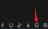
After opening the terminal, enter the idf.py save-defconfig command.

After pressing the Enter key to execute the command, you will notice that a new sdkconfig.defaults file has been added to the project.
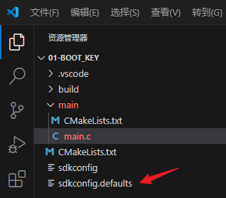
Click to open the sdkconfig.defaults file, and you will be able to view its contents. This file contains the modifications you made to menuconfig.
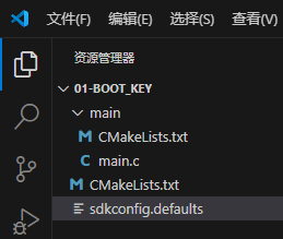
At this point, you can remove all the folders generated during the configuration and compilation process in the project. The final files are as follows:
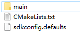
Use VSCode to reopen the project. After selecting the target chip, the configuration in the sdkconfig.defaults file will be configured into menuconfig, eliminating the need to manually configure menucofig. This routine only configures the FLASH size. In subsequent routines, there will be more and more configuration content in menuconfig. At that time, this file will become necessary.